-
tél : +86-592-6382791
-
e-mail : sales@pidmaxwell.com
tél : +86-592-6382791
e-mail : sales@pidmaxwell.com


What Is PV Retransmission in a PID Temperature Controller?
Process value retransmission, or PV retransmission, is a temperature-controller function that converts the measured temperature into a proportional analog output, commonly 4–20 mA. A PLC, recorder or remote indicator reads that signal to monitor the temperature while the controller continues regulating the process locally. On suitable models, retransmission and heater control operate through separate outputs.
For example, an oven controller can use its solid-state relay drive output to control heating and send a separate 4–20 mA temperature signal to a factory monitoring system. The local controller handles temperature regulation; the monitoring system displays or records what is happening.
This feature is also called process value re-transmission, analog retransmission or a PV transfer output. The important question is not simply whether a controller has an analog output, but what that output represents.
PV retransmission is not the same as the PID control output
Three values have different jobs in a PID temperature controller:
The PID algorithm uses the difference between the measured temperature and the setpoint to adjust the control output. PV retransmission reports the measured temperature instead. Some controllers can retransmit the setpoint or output demand as alternatives, so the selected retransmission source matters.
Consider an oven warming up toward 200°C. The PID may initially demand high heater output. As the oven approaches its target, the demand normally falls. With PV retransmission selected, the monitoring signal follows the measured temperature—not the changing heater command.
A controller described as having a “4–20 mA output” could therefore provide a temperature signal or a control-demand signal. Those functions are not interchangeable. An SSR drive output is different again: it is a switching command, not a linear temperature-retransmission signal.
How does process value retransmission work?
The controller first measures its input, typically from a thermocouple or resistance temperature detector, such as a Pt100 RTD. It processes that input into a temperature value for display and control.
When PV retransmission is enabled, the controller also maps that measured value to a configured analog output range. A digital-to-analog conversion stage produces the corresponding current or voltage signal. The receiving device converts the signal back into engineering units, such as °C.
The result is a separate monitoring path alongside the control path:
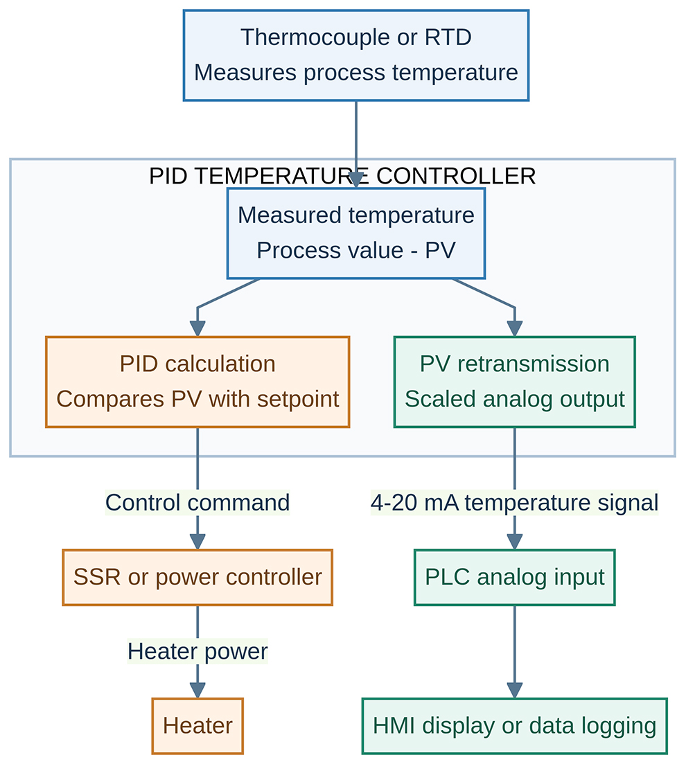
The PID control path adjusts heater power. The PV retransmission path reports measured temperature to the monitoring system. This is conceptual signal flow, not a terminal wiring diagram.
The receiver does not need to calculate PID control just to display the temperature. In this arrangement, the local controller remains responsible for the temperature loop, while the PLC or recorder uses the retransmitted value for supervision or recording.
A practical 4–20 mA scaling example
Suppose a controller is configured to retransmit 0–400°C as 4–20 mA. The bottom of the temperature range corresponds to 4 mA, and the top corresponds to 20 mA. Values between those endpoints are proportional.
For a normal forward-scaled range:
Output current in mA = 4 + 16 × (PV − L) / (H − L)
Here, PV is the measured temperature, L is the configured lower temperature endpoint, and H is the upper endpoint.
For the 0–400°C example:
The PLC reverses that relationship:
Temperature = L + (measured current in mA − 4) × (H − L) / 16
Both ends must use the same scaling. If the controller maps 0–400°C to 4–20 mA but the PLC interprets the signal as 0–800°C, a correct 12 mA signal will display as 400°C instead of 200°C. A scaling mismatch can therefore look like a measurement fault even when the analog output is working correctly.
The retransmission span may be configurable separately from the sensor’s full measurement range. Check the controller manual rather than assuming the thermocouple range determines the output scaling. Output behavior below or above the configured span is also model-dependent.
Why use 4–20 mA instead of a voltage signal?
A 4–20 mA output is useful when the receiving PLC, recorder or indicator already accepts industrial current signals. Within the output’s permitted load and voltage limits, the current represents the measurement despite voltage drops in the wiring. The total receiver burden and cable resistance must still remain within specification.
The 4 mA “live zero” is another useful characteristic. In a correctly configured loop, 4 mA represents the lower measurement endpoint rather than no current. A broken output-loop wire can produce zero current, allowing a suitably configured receiver to identify a fault rather than treat it as a normal low-end temperature.
That does not mean a broken thermocouple always produces zero current. A sensor failure occurs upstream of the retransmission loop, and its output indication depends on the controller and configuration.
A linear voltage signal, such as 0–10 V, can also be appropriate when supported by the selected controller and receiver. Match the actual output option, receiver input impedance and grounding arrangement. Do not confuse a pulsed SSR drive voltage with a linear 0–10 V retransmission output.
Typical applications for PV retransmission
Industrial ovens, dryers and heat-treatment recording
An oven can regulate temperature locally while sending its measured value to a paperless recorder or data-acquisition system. The recorded trend helps operators review warm-up, holding and cooling behavior. Watlow documents a heat-treatment oven feeding a chart recorder as a retransmission application.
This arrangement is useful when a machine needs both convenient panel control and a separate temperature history. The recorder must have a compatible analog input and matching scaling.
Plastics machinery and multi-zone temperature monitoring
An extrusion line or other multi-zone machine may use a separate PID controller for each heating zone. Each controller can send its PV to a PLC analog-input channel, allowing a central human-machine interface, or HMI, to show all zone temperatures together.
Local control stays with each controller. Operators gain a consolidated view of zone temperatures without requiring the PLC to execute every temperature-control loop. For larger installations, compare the analog channel count and wiring effort with a digital communications solution.
Packaging, food-processing and curing equipment
A packaging machine may need to display sealing-jaw temperature on its main HMI while a dedicated PID controller regulates the heater. A curing or drying oven may need to record the actual temperature alongside cycle events.
PV retransmission provides the measurement signal for these tasks. It does not, by itself, establish food-safety compliance, product-temperature validation or a validated batch record. Those depend on the complete process, sensor placement, calibration and recording system.
Remote indication and equipment retrofits
A machine may already have a reliable local temperature controller but lack a central temperature display. If the controller supports the required retransmission option, its PV can be sent to a remote indicator or PLC without replacing local control with a new control architecture.
This is particularly useful where existing monitoring hardware has spare analog inputs. It can also avoid adding another sensor solely for routine display, provided an independent measurement is not required for safety, validation or diagnostics.
How to connect and configure PV retransmission
Terminal assignments and setup menus vary. Use the wiring diagram for the exact controller model, panel size and installed output option—not a generic diagram from another series.
Also check retransmission accuracy and update rate. They are not necessarily the same as input accuracy, PID execution rate or display refresh rate. Filtering can smooth a noisy reading but may delay its response. The overall remote measurement depends on the sensor, controller input, retransmission output and receiver—not just the controller’s display resolution.
PV retransmission is not independent overtemperature protection. It normally depends on the same controller and measurement chain used for regulation. Where the machine’s risk assessment requires independent protection, use the appropriate separate protective system and sensor.
PV retransmission, Modbus or a separate transmitter?
PV retransmission is a good fit when the receiving system needs a continuously available analog representation of one selected value and already has a compatible input.
Digital communication, such as RS-485 Modbus, is often more useful when the system needs several values from each controller, alarm status or remote parameter access. It requires compatible communications settings, register definitions and integration. Analog retransmission does not provide those extra data simply because it carries the temperature.
A separate temperature transmitter may be preferable when only measurement transmission is required and there is no need for local PID control. An independent sensor and transmitter may also be needed when the design calls for a genuinely separate measurement channel. Retransmitting a controller’s PV is not an independent check of that controller’s sensor.
Choosing a Maxwell temperature controller with PV retransmission
When selecting from Maxwell’s PID temperature controllers, specify the monitoring requirement as well as the control requirement.
The Maxwell MTA series PID temperature controller offers optional process-value retransmission. Its product information explicitly describes sending the PV as a 4–20 mA signal to a PLC or paperless recorder. Retransmission availability and the required output combination should be confirmed when ordering.
For a suitable configuration, tell our team your sensor type, operating temperature range, required heater-control output and the receiving device’s input specification. Also identify whether isolation, remote communications or a particular sensor-fault response is required.
Need local PID control and a temperature signal for your PLC or recorder? Contact Maxwell at sales@pidmaxwell.com with your application details to discuss the appropriate controller and retransmission option.
Frequently asked questions
Can a PID controller control temperature and retransmit PV at the same time?
Yes, if the selected model and installed output configuration support both functions. A common arrangement uses an SSR drive or relay output for control and a separate analog output for PV retransmission. Confirm the available combination before ordering.
Does PV retransmission improve temperature accuracy?
No. It makes the controller’s measurement available elsewhere. The retransmission output and receiver introduce their own conversion errors, so the remote reading must be evaluated as a complete measurement chain.
Can one retransmission output feed several devices?
Do not simply split the wiring. Current loops are not distributed like ordinary parallel voltage connections. Use an appropriately specified signal splitter or isolator, or have a qualified designer verify a permitted arrangement against the instruments’ load, grounding and isolation requirements.
What happens if the temperature sensor breaks?
There is no universal PV retransmission fault current. Check the exact controller manual and configuration, then verify that the receiver can recognize the resulting condition. A broken sensor is not the same fault as an open 4–20 mA output-loop wire.

adresse : NO.201 Binhuyili, HaiCang district, XiaMen,FuJian, China 361026
Max liao: +8618150368619(whatsapp)
e-mail : sales@pidmaxwell.com
numériser via wechat
Scan to Whatsapp